Part 2: FIRMWARE
While the proper hardware design and layout guarantees the correct radiation and reception of the RF signal, the software (sometimes referred to as firmware) plays a fundamental role in the reliability of the message being carried by such signal.
As briefly mentioned before, the RF modules have no intelligence included, so it must be provided by the microcontrollers’ software. This intelligence includes the selection of the proper coding protocol, the link speed (bit rate), data organization and error detection/recovery mechanisms.
The Manchester Code has proved to be a basic but very reliable way to send data through a radio link, so this will be the chosen protocol. Speeds up to 5000bps have shown good stability, being the top bit rate of our link; a lower speed option will be available for added versatility. The data will be organized in a macro-structure called “frame” for transmission, and an error correction byte will be included.
The software has been designed in a modular way, with all the essential functions organized in “drivers” that will remain unchanged. The user has complete freedom to implement any routine in the main area, and when ready to transmit, just call the TX driver, and the information will be sent; on the receiver side, the RX driver also takes care of all those complicated tasks, returning just the useful data to the main program.
There are several protocols to send data over a radio link, each with its particular pros and cons. One of these protocols is called the Manchester Code, and its logic is quite simple:
“Every bit is represented by a transition, instead of a logic level”.
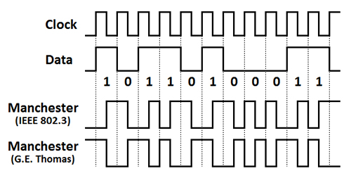 FIGURE 1.- Manchester Code logic and conventions
Figure 1 shows the logic behind the Manchester Code and the two conventions to represent each bit. We will be using IEEE 802.3 definition, so a logic “1” will be represented by a “low to high” transition, while a logic “0” will be the opposite (“high to low”). The advantages of this form of coding are quite obvious:
1- The signal clock is always present in each transition, no matter the bit sequence, and it is easily recovered at the receiver end.
2- The average DC level of the signal is constant, around 50%.
3- Using an OOK (On-Off Keying) RF link, like the one we use here, the average transmitting power is reduced. This is useful not only to save power in portable applications, but to be within the power limits mandated by local laws, while the peak power may be larger to increase range.
Linx modules are rated up to 10000bps; while this speed is possible, our link will have a maximum speed of 5000bps. This is due to the coding, since each bit will have 2 logic levels; if we used a simple binary transmission (“1” represented by a high level and “0”by a low), then the bit rate would double, reaching 10000bps. However, given the advantages I already mentioned of the Manchester Code, I am willing to sacrifice transmission speed for simplicity and reliability. As a matter of fact, the speed of 5000bps proved to be absolutely reliable reaching distances in excess of 600ft. A lower speed (2500bps) is provided to be used in case of very noisy environments or to reach longer distances. Linx claims that distances up to 3000ft are attainable, with the proper hardware setup.
The data to be transmitted is composed by three elements, 1-byte long each: ADDRESS, DATA and CRC.
The first element, ADDRESS, indicates to which receiver the transmission is intended to, or what function within a single receiver is being called… or even a combination of both. Being 1-byte long, there are 256 possibilities; usually too many to be used simply to indicate the intended receiver (unless you plan to have hundreds of receivers for the same transmitter). So the most efficient way would be to use the ADDRESS byte to indicate receiver and function:
1- Upper nibble (4 bits) used to call the receiver (16 possibilities).
2- Lower nibble used to call the function within the receiver (16 possibilities).
So it is possible to indicate that the receiver number 5 performs function number 9, which may be, for example, to turn on a servo mechanism, and position it based on the contents of DATA.
In our example code ADDRESS will be used simply to indicate the receiver; it will contain the number 15, just to show how it may be used; at the receiver side, when 15 is read from the ADDRESS byte, the rest of the data will be considered valid and executed by the code. The selection of 15 is simple; in binary form: 00001111. So it is easy to “see” this code in an oscilloscope; in Manchester Code: 10 10 10 10 01 01 01 01.
However, despite the simplicity of the provided example code, please be aware of the power you have by properly using this ADDRESS byte. It will also be extremely useful when trying to send more than 1 DATA byte; the lower nibble may be used to indicate which byte you are sending, so the receiver can properly reassemble the complete DATA.
The DATA byte, as it name implies, carries the actual information to be delivered; it could be a fixed value, such as an order to execute a defined task, or a variable one, like the output of an A/D converter.
Being just 1-byte long it may seem very limited, particularly when sending large pieces of information; it is not, if we use the techniques previously described with the ADDRESS byte.
Our example code will send a different DATA byte based on the status of PIN A3 (RA3/AN3/CMP1, pin 2): if low, DATA will contain a fixed 1; if high, DATA will alternate between 0 and 1, using an internal timer to control the change. On the receiver side, this will be used to turn the provided LED ON (1) and OFF (0). This is a very simple way to test the link and demonstrate how to use the DATA byte.
Can we send more than 1 DATA byte at the same time? It is possible, and, as we will see later, that is much more efficient than sending only one byte at a time. In this example I try to demonstrate the basics of the RF link; but a few changes in the code will allow any number of DATA bytes to be sent at once, although that is beyond the scope of this article.
CRC, short for Cyclic Redundancy Check, contains information useful to validate the previously received DATA byte (or bytes) and may provide elements to recover any missing bit. The several methods and algorithms used to create the CRC byte are way beyond the scope of this article, but I included this byte because a proper data stream should have one. You may include a CRC calculation routine in your code, and the CRC byte will be sent; but for the purposes of this example, I just made CRC = DATA. At the receiver end, if CRC is not equal to DATA, you know that something went wrong and DATA may not be valid; however, there is no way to tell which one is wrong.
Now that the main three elements have been described, let’s review how they are sent. They will be put together, one after the other, in a macro-structure called “frame”. So inside the frame we will have, in order, ADDRESS – DATA – CRC.
Any RF link is susceptible to noise, from other transmitters or just interference from unintended sources, like motors or switching power supplies. So the receiver must have elements to decide when a valid frame is being received and where it starts. For this reason, a “frame synchronism” is added in front of each frame. This synchronism is a known sequence, unchanged, that cannot be emulated by any combination of the previously described three bytes.
In our case, we will be using 20 “1” (logic one) followed by “0” (logic zero). In binary form: 111111111111111111110.
What happens if ADDRESS and DATA are 255 (all “1”) and CRC is 11110XXX? There will be a sequence that can be taken as the frame synchronism, giving very bad results. That will not happen (in an “error-free” transmission) since there is another element added to the frame: a “spacer” between bytes. This is a short sequence, just “1” and “0”, added at the end of each byte. So the previous “conflictive” sequence will have: 11111111 10 11111111 10 11110XXX 10. So the long “1” sequence is broken by the spacer, thus guaranteeing that no combination will emulate the synchronism sequence.
Figure 2 shows a complete frame and its components, in Manchester Code.

FIGURE 2.- Complete frame structure
As you may have immediately noticed, bit-wise this link is quite inefficient: we need 51 bits to send just 8 DATA bits. As mentioned before, a more efficient frame would include more DATA bits; the more DATA bits you send per frame, the more favorable the relationship between total bits and the DATA bits will be. All you need is to grasp the basics; this increase in efficiency will be just a few lines of programming code away!
Previously I briefly mentioned the bit rate, 5000bps as the top, with 2500bps also available. The selection of the transmission speed is done at the transmitter end, and the receiver should be able to do the same, either manually or automatically. In our design, the transmitter selects the bit rate based on the status of PIN A2 (RA2/AN2/Vref, pin 1): if low, speed will be 2500bps; if high, 5000bps. At the receiver end the speed detection is automatic, performed by the provided code. Since this detection is based on time measurements, using the local oscillator as the reference, it is very important to keep the 20MHz crystal unchanged, as mentioned in the hardware section. While the code will adapt itself to other speeds, the reference values will be different and the signal may not be properly decoded. So for the sake of simplicity and a reliable link, keep the same oscillator at both ends, working at 20MHz as already described.
When we later analyze the actual code, we will notice that the transmitter needs to send the frames at certain intervals for the link to work; an isolated frame may not be received, and the same will happen to frames spaced more than 10 to 15 milliseconds (ms) apart. Why? The receiver must be “awake” and with the right gain settings to properly receive and demodulate the signal. After 10ms or more of inactivity, the receiver may not be ready for an incoming frame.
The solution is to send the frames repeatedly at intervals of 10ms or less; between transmissions, you may perform additional tasks in both microcontrollers.
While this works, and is presented like this in the example code, the proposed solution has two major drawbacks:
1- If you need to perform tasks that require more than 10ms, such as reading an ultrasound sensor to measure distances, you will not be able to comply with the required frame repetition rate.
2- Besides transmitting power (as previously mentioned) local laws may regulate the time a given transmitter, working at a set frequency, can operate continuously. In the US, the FCC regulates transmissions in the so called “license-free” bands, and estipulate that the transmission cannot be continuous, but in bursts, spaced a set time apart.
These reasons – specially the second – mandate that an actual device built with this link, either for commercial purposes or personal use, must not transmit continuously. The solution is simple: perform a minor change in the code, set an internal timer in the main program, and transmit 2 or 3 frames in a single burst, spaced 10ms or less apart from each other; then let the transmitter “rest” for a few seconds. The provided example is only to show how the link works and to make a functional test. The main code should not be used by an actual device as is; however, the transmitting and receiver routines, undoubtedly the most complex portions of the code, will work unchanged, just as I present them.
Please check your local regulations so your final device is fully compliant.
Transmitter software (TX)
Both transmitter and receiver software have been created to be portable; that is, the fundamental transmitter and receiver routines have been grouped in a separate file, like the “drivers” of the hardware. These routines will remain unchanged, no matter the application, and they contain the most complex parts of the code.
The main program, with only a few lines to perform the previously described basic functions, is provided to show how the link works. Here is where the user will write his/her own code, take advantage of the power of the microcontroller being used, and when ready, just call the transmitter / receiver functions.
All software has been written in C, using the CCS C compiler. It should be possible to transport the code to other C compilers without big changes, since most of it is standard.
Let’s examine the transmitter software now; please read the comments added to the actual C files for additional information (available in the download section).
Files:
1- Manchester_Link_TX.c – main program.
2- Manchester_Link_TX.h – PIC setup.
3- MAN_TX.c – transmitter driver.
The main program is quite simple; after the initial definitions the program enters an infinite loop, where PIN A2 is read to set the bit rate, ADDRESS fixed as 15, PIN A3 is read to decide the value of DATA and then CRC made equal to DATA.
With all four variables set, the transmission function is called:
- mc_tx(baud, address, data, crc);
Here is where the main program sends the variables to the transmitter driver; no matter how simple or complex the main program may be this is the only line required to transmit the information. The user has total freedom to write any code here; when ready to transmit, just call the function.
The last line is just a 1 millisecond delay to start all over again. As previously stated, this is just a working example; practical applications may not use continuous transmission and should follow local regulations regarding the usage of the radio spectrum.
The transmitter driver is the true value of this design. It will remain unchanged, no matter what application the user may come up with. It needs to be included in the main program at the very top, after the PIC setup:
- #include “MAN_TX.c”
The driver contains all the elements to create a frame in Manchester Code, using just the four variables received from the main program.
The bit rate, expressed as thousands of bits per second is converted into half bit time (“semiperiod”), so the Manchester Code is easily obtained: a “one” will be one “semiperiod” low, one high; a “zero”, just the opposite.
The frame synchronism is easily constructed just calling the function “one” twenty times, and then “zero”.
Each byte (ADDRESS, DATA and CRC) is analyzed bit a bit, starting at the MSB side, and depending on the result, the proper function is called (“one” or “zero”), inserting the spacer after each complete byte.
And that’s it! A complete frame, with all the bells and whistles previously described, is sent out of PIN A0 (RA0/AN0, pin 17), towards the voltage divider and the transmitter module, at the speed set by the bit rate variable.
The user will never need to change this driver program to send a standard frame; if more DATA bytes have to be included in the frame, only a few changes will be required.
A final note: please check the names of the few variables used here, just not to use them in the main program to avoid conflicts. In most cases I used the suffix “_tx” to name them.
Receiver software (RX)
Similar to its hardware counterpart, the receiver software is just a little more complex than the transmitter. But there is nothing to worry about: the complexity resides in the driver, which may never need to be touched by the user. The same three-file structure is maintained here:
1- Manchester_Link_RX.c – main program.
2- Manchester_Link_RX.h – PIC setup.
3- MAN_RX.c – receiver driver.
Again, the main program is quite simple, since it is only provided for demonstration purposes; this is the space for the user to be creative.
Please note that the driver is included at the top, as we discussed in the transmitter section:
- #include “MAN_RX.c”
Then the standard definitions before the main program; note that the Interrupt Service Routine (ISR) function is defined:
- void detection_isr();
This is important since the received information will come through PIN B0 (RB0/INT, pin 6), by triggering the external interrupt, on the rising edge (low to high); the program will land in this function as soon as such edge is detected.
Another important line that must be included, now inside the main function, is the setting of the “timer0”:
- setup_timer_0(RTCC_INTERNAL|RTCC…
This is required to program the “timer0” as 8-bit long, being incremented every 1/16th of the instruction clock frequency. This internal timer will be used to determine the bit rate of the incoming signal, by measuring the length of one bit.
Since we already mentioned the use of interrupts, these must be enabled:
- enable_interrupts(GLOBAL);
Then the program enters an infinite loop, which only enables the particular interrupt and its condition. Nothing else is done here. The user may add many more lines at this point, provided none of the activities disable the interrupts; remember that the receiver is waiting for a signal to arrive.
When a rising edge is detected, the program jumps to the ISR function. As usual, the first thing to do is disable the interrupts, and immediately the reception function is called:
- frame=mc_rx(frame);
This function is located in the receiver driver, and it returns a 32-bit variable: “frame”.
The beauty of this software is the simplicity: a signal arrives, the “mc_rx” function is called, and “frame” contains all the information that was received.
Being a 32-bit variable, “frame” can contain 4 bytes; these are ADDRESS, DATA, CRC and HALFTIME of the received frame.
This is all we need; we have received and decoded the information and it is ready to be used at the receiver side.
How to extract each byte from “frame”? It is very easy, based on the nature of each variable. While “frame” is a 32-bit variable, all others are just 8-bit long. If we make something 8-bit long equal to another object 32-bit long, the first one will be capable of keeping just the 8 least significant bits (or byte) of the second. So when we put:
- halftime=frame;
HALFTIME will only receive the least significant byte of “frame”. If we later move the contents of “frame” 8 bits to the right and repeat the process, the next byte can be extracted, and so on.
While the contents of ADDRESS, DATA and CRC are already well known, I have not mentioned what HALFTIME contains; as the name implies, it has the duration of half a bit, so the bit rate can be calculated from there.
The rest of the instructions show how to use the received information, in a very basic way. If there is an error in the received frame, the function will return a 0, as we will see later. So HALFTIME will be 0; this is used here to set the error flag.
If ADDRESS is 15 (as set in the transmitter) and there is no error, then DATA contents are used to set the LED ON and OFF. CRC is not used in this brief example.
Here is where the user has absolute freedom to implement complex coding, including routines that may disable the interrupts, such as writing the received characters in an LCD module.
This is all you have to know to use the receiver; for those interested in knowing how the frame is actually received and decoded, let’s analyze the receiver driver.
All the complexity of the link resides in the receiver driver; you may notice that the actual file is much longer than the rest. However, please note that most of the text is comments; I explained each section so it is easy to understand, and those users that would like to tweak the driver will have enough information to do so.
The reception function, “mc_rx”, called from the main program, is the one to call all the rest of the “bit-gathering” functions.
The first thing to do is detect the bit rate; this is the task of “baud_detect” function, performed by counting the duration of two halves of one bit. In fact, it is the second half of one bit, and the first of the next. You may remember that all these activities are triggered by a rising edge of an incoming signal; now imagine that this signal is an actual frame. The first bit of a frame is a “1”, in Manchester Code, low to high; so, when the interrupt is triggered, the first half of this first bit is already gone. For this reason, “baud_detect” measures the last part of this bit, and the first part of the next one (the second bit of the frame) to have one complete bit’s time.
Shouldn’t it be enough to measure just one half, since the bits are symmetrical? Yes and no. If we send data continuously, one frame after the other with no delay between them, the receiver will be continuously active and the internal DC levels will be stable. In this case, the bits are fairly symmetrical. However, if the frames are spaced, let’s say by 10ms, the receiver may not be completely ready when each new frame arrives. As a consequence, the first bits of the frame may not be symmetrical, as shown in Figure 3, obtained by spacing the frames 10ms apart. While the link still works, if we do not measure a complete bit to recover the bit rate, there is a real possibility that we have the wrong figure, thus making any subsequent bit detection impossible.
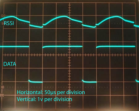 FIGURE 3.- Actual received signal with frames spaced 10ms apart
In our example code we send the frames 1ms apart, so there is no major issue; however, the “baud_detect” function has been designed with those extreme cases in mind.
Back to the software, after the first half of the second bit “timer0” will contain the bit duration… kind of. As previously mentioned “timer0” increases every 1/16th of the instruction clock. Some simple math here:
1- 20MHz oscillator means 5MHz instruction clock.
2- The period of 1 cycle is 1/5MHz, which is 0.2 microseconds (µs).
3- “timer0” will increase 1 count every 0.2µs x 16 = 3.2µs.
4- 1 bit, at 5000bps, lasts 200µs; so at the end of 1 complete bit “timer0” = 200µs/3.2µs = 62.5.
Being an 8-bit integer, “timer0” may either have 62 or 63… well, this is irrelevant. By nature, radio signals will experiment a phenomenon called “jitter”. This is the random shift of the edges (transitions) of the signal, shortening or stretching the bits. So “timer0”, instead of a fixed, single value, may have any of several values surrounding the central point, at 62.5. When any of these values is reached, we assume that the actual bit length is the one calculated. The program implements this by accepting a range, between 55 and 70; if “timer0” is within this range, 1 bit duration is 200µs, so half bit will be 100µs. And this is exactly what is stored in the variable “semi”, returned by the function, and from now on known as “semiperiod” (familiar name?).
I will not repeat the calculations, but it is easy to understand that for 2500bps the “semiperiod” is 200µs, and the detection range for “timer0” is 118 to 133.
Now that the bit time is known, the detection of the rest of the bits is easier. The strategy is simple: read the status of the signal – wait until it changes – read next status – compare status 1 and 2. This is possible since we know that every bit will have a change of status in the middle. Before reading the next bit, we wait a time called “semiandjitter”… just the half bit period plus the potential jitter, to make sure that when we read again we are actually reading the next bit and not the “tail” of the previous. You may see that the original signal clock is implicit in this transition, as it was mentioned, one of the advantages of the Manchester Code. In a hardware receiver, these transitions will synchronize the PLL, to reconstruct the clock and extract the bits.
Knowing how each bit is coded, if status 1 is greater than status 2 (high to low transition), the received bit is “0”; otherwise, it is “1”. In the actual code, these “status” are called “in1” and “in2”.
Then, you simply add this recovered bit to a 32-bit variable (“three_byte_rx”) and shift it one place to the left, so it is ready to accept the next bit.
By carefully eliminating the spacers, “three_byte_rx” will contain ADDRESS, DATA and CRC; being a 32-bit variable, 8 bits are empty… true, but there are no 24-bit variables here.
Back in the “mc_rx” function, if there is no error in the process, “three_byte_rx”, now called “ad_da_cr_rx” is moved to “frame_rx”, another 32-bit variable. Its contents are then shifted 8 bits to the left (x 256) and “semiperiod” added. “frame_rx” is now ready to be returned to the main program, where it will be known simply as “frame”.
As we presented earlier, in case there is any error, the routine tells this condition to the main program by sending an empty “frame_rx”.
And this is the essence of the receiver driver. Please refer to the actual file where there are plenty of comments in each function as well as the overall concept.
A final note: as with the transmitter program, please check the names of the variables used here, just not to use them in the main program to avoid conflicts. In most cases I used the suffix “_rx” to name them.
Improvements and applications
While the link is fully functional, and proved to be extremely reliable during the various tests I have performed, there is plenty of room for improvements and customizations.
Let’s continue with the improvement discussed in the transmitter section: how to send more than 1 DATA byte. These additional bytes could be easily added to the frame, one after the other. At the receiver end, you just need to know how many to expect, so not to miss any of them. Obviously a single 32-bit variable will not be enough to store all of them; they can be stored in individual 8-bit variables. How to return them from the driver to the main program? One variable will not be enough, so a “structure” should be considered.
This is just an example, but there may be many. My intention was to show a working link, present the essential components and demonstrate how to handle them in software, within a very reliable hardware layout, offering the flexibility given by the full access of most of the microcontroller’s and RF module’s pins.
The applications are endless, limited only by the user’s imagination; this is just a building block for many bigger projects.
Figure 4 shows how to use the receiver with an LCD display. The receiver hardware is mounted on a breadboard (one of its biggest advantages, as explained in the hardware section) and wires are run to the display. To the left, there is the regulator to obtain 5v from a 9.6v RC car battery, and a simple low battery detector. In the display you can see that:
1- ADDRESS = 15.
2- DATA and CRC = 1.
3- Bit rate (B) is high (H = 5000bps).
4- Error (E) = 0 (no error).
Since there is no error, ADDRESS is 15 and DATA is 1, the LED on the receiver hardware is ON.
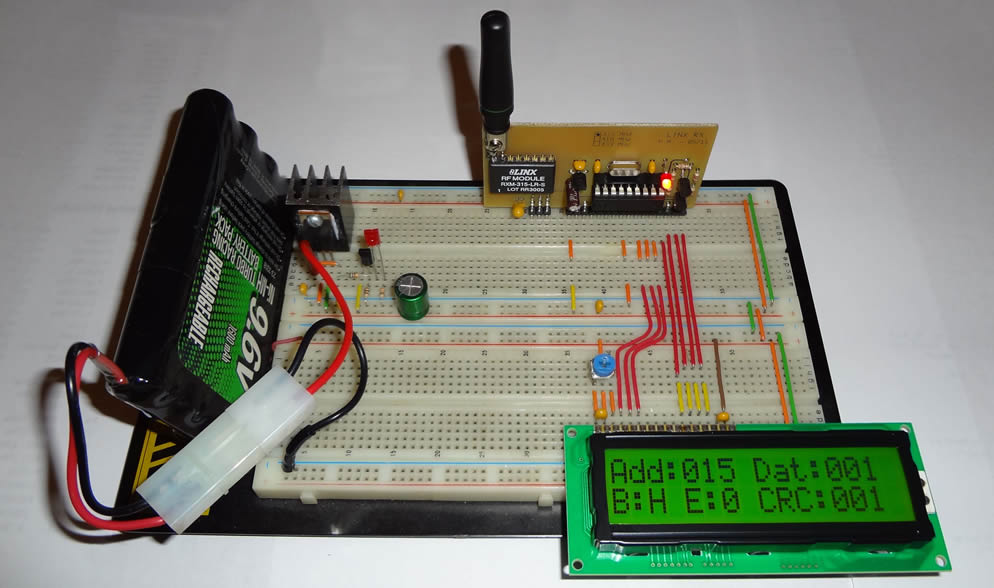
FIGURE 4.- Receiver with LCD
This simple application shows the potential of these units, and it has been very useful to debug the code when things were not as expected.
This concludes the second and last part of this article. Should you have any questions, concerns or just comments regarding the hardware or software presented, do not hesitate to contact me at mmaggi@hotmail.com or visit my web page www.magusporta.com; PCB artworks and software routines are available for direct download.
Acknowledgments
I would like to extend my gratitude to the individuals and companies that supported me during the various phases that this project involved:
- To my wife, Silvia, for proof-reading the entire article, and setting the web page so the material is readily accessible for download.
- To my brother, Pablo, for the constant help to make the software do what it was supposed to.
- To Linx Technologies, for providing information, samples and kits to evaluate their products.
- To Microchip, for providing samples to test several PIC microcontrollers, confirming the true “general purpose” of the units.
References
This article has been created using information provided by the various manufacturers in their web sites, such as data sheets and product specifications. Please refer to them for the actual documentation and additional information:
- RF products: Linx Technologies (http://www.linxtechnologies.com).
- PIC microcontrollers: Microchip (www.microchip.com).
- PIC C Compiler: CCS (http://www.ccsinfo.com).